| The Table Top Tesla Coil |
|
This is a high voltage project. High voltage is lethal! Do not replicate my experiments if you're not qualified to work with high voltage! It's time for me to present to you my Table Top Tesla Coil. I had my fair amount of concern while building this contraption, as everybody else on the net start their build with a Java based calculator. At first I didnt think that a tesla coil mockup without the calculations would be a success but I proved myself wrong! The working principle of a tesla coil is very simple. Let's take a look on the schematic below:  click to enlarge... An AC power supply, here a neon sign transformer creates 15kV. The transformer will charge the capacitors. As they charge up, the voltage across the spark gap will rise. Eventually the potential across the spark gap will be large enough so that a spark will jump across the gap. When this happens, a closed loop through the primary coil will be formed. Whenever you have a coil and a capacitor you have an oscilating circuit. (just like the ignition system of your car) These oscilations through the primary coil will then again induct an extremely high voltage through secondary coil. The process above repeats itself every time the capacitors has been dischaged across the spark-gap. Back to building my coil. I quickly desided to toss away the Java based calculators, and start doing som fabrication. I took an old 50 mm PVC pipe and wound 1200 windings of Ø.25 mm insulated copper wire on the PVC tube. I used the workshop lathe to help me make the windings. They must be placed perfectly on the PVC tube, witn no spacing between the windings, and no overlap. Afterwards I turned a little copper spike on the lathe to put on top of the tesla coil. A toroid should be fitted on this spike, as it will build up a charge on its surface (a kind of capacitor) but I never took me the time to make one. The primary coil was wound using a Ø5 mm copper brake tube from a local auto parts supplier. It has 5.5 windings an was initially designed to be at a 45 degree angle from the tesla coil, as this helps to prevent charges jump between the primary- and secondary coil. I had to leave it at a steeper angle or else I woulden't have enough length of tube. For the same reason as with the 45 degrees angle, I gave the secondary coil many many layers of lacquer. (the sticky kind that's used for floor boards. Using spray based lacquer, it will take forever to build up a decent 2-4 mm layer.) The transformer I used was an old 2kV micro wave transformer. The spark gap is from the starter-circuit of an old scrapped TIG welder. First I connected the transformer and spark gap to some metal film capacitors that were rated at 4500 volts. The Tesla Coil ran fine for a short time, but then they started to pop, one by one. The solution was to take one large capacitor in a ceramic housing from the same TIG welder as mentioned above, that was rated to 7.5kV. That did the trick! The capacitor now runs cool and stable. Here's the tesla coil: 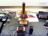 click to enlarge... And here's some stats: Overall build time: 3 days Spark length (to a ground wire): 10-12 cm Spark length (to air, ungrounded): 2-3 cm Runtime before overheating the spark gap: 4 minutes Finally, what you've all waited for, the videos: Powering a neon tube wirelessly, and sparks to air. 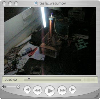
click to enlarge... Sparks to a grounded wire. 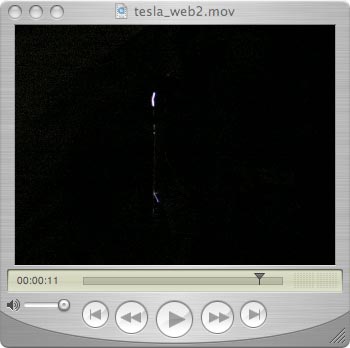
click to enlarge... Hope you enjoyed it. |