| Build your own 3D scanner |
|
The only things we need to make a DIY 3D scanner is a webcam and a computer controlled rotating table. We want to build a table looking like this: 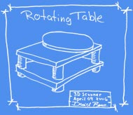 click to enlarge... When the rotating table is constructed, we're able place an object on the table, and use a technology called discreete light to create a 3D model of it. The following blueprint shows an exploded view of the vital components of the rotating table. I use an R/C servo to rotate the table. It would be easier to construct a table using a steppermotor, but I had an R/C servo on the shelf. The servo cannot rotate a full 360 degrees, so I use a oneway bearing to be able to rotate the table 180 degrees (which is the limit of the servo), and then move the servo back to it's inital position. Now I can rotate the table another 180 degrees. A decent grade oneway bearing works without any slack at all. I will not go into details with construct the circuitry, and it's allmost as cheap to buy a servoboard from www.picobotics.com as it is to build one yourself. I've just learned that the picobotics website has been shut down. I fear they have gone out of business. I'll post a tutorial on how to build your own controller board during fall this year 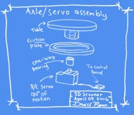 click to enlarge... From the top down the components are as follows: 1. The table which will be made in aluminium, turned on the lathe. 2. A friction plate on which the table rests. The friction between this plate and the table makes makes sure that the table don't move back when rotating against the direction of the oneway bearing 3. The oneway bearing 4. The servo Here's two pictures of the finished scanner consisting of the rotating table and controllerboard: 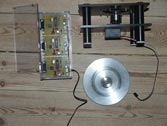 click to enlarge... 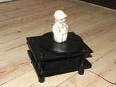 click to enlarge... Place a lightsource at a 90 degree angle to the webcam's viewing angle. A script is programmed to do the folowing: Take a picture with the webcam, rotate the table one degree, take another, rotate one degree, etc... As mentioned earlier the 3D scanner takes advantage of a technology called "structured light". When you look at the picture below, it's very easy to destinguish the contour of the porcelain figure from the background. This is used when processing the 360 images captured using the above method. 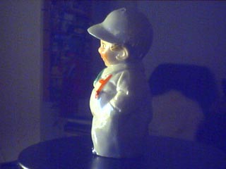 Here's the final result. All 360 pictures have been processed by an algorithm written in Matlab 7 R 14. I'ts just a rough algorithm which detects the contour of the scanned object and plots 360 curves along the y-axis in the coordinate system. Then the algoritm wraps a surface around the lines, and then the image processing is finished. The algoritm is crude but the result is stunning! I am currently working on an algoritm that makes it possible to export the 3D figure from Matlab til an .STL file. The .STL format is compatible with 3D CAD applications such as ProEngineer and AutoCAD Mechanincal Desktop. You will find the Matlab files in the software section 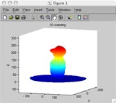 click to enlarge... I hope you liked this little guide. The scanner sure was great fun to develop, design and build! I'd like to thank my friend Rasmus for helping during the development of the scanner. |