| Poor man's FM transmitter |
|
Please note that in some countries it is illegal to transmit radio on the FM band without a license. You know these smart FM transmitters you can use to stream music from your iPod into your car stereo? Here's a nice little project that I've made and that you can build yourself for around 5$. It's my homebuilt FM transmitter that I usefor streaming music into my car stereo and the old-school stereo at the metal workshop at my university! The awesome thing is that the transmitter is based on only one transistor, and is really simple to construct. Here's a picture of the finished FM transmitter: 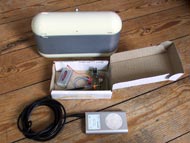 click to enlarge... So how is the sound quality? Well... It's mono, but actually fairy good. Check out this video and hear the sound quality and see the working principle: click to download... Building the FM transmitter is fairly easy. You need to fabricate two parts yourself: -The coil. Grab some 0.8 mm copper wire (Slaughter an old transfomer. That's how I got hold of a decent length) and wind it 4 turns with an inner diameter of 5 mm. Wind it with no spacing between the turns and use some kind of 5mm rod to wind the coil around. I used a phillipshead screwdriver that was 5 mm in diameter. -The antenna. Just cut approx 12.5 cm of insulated wire or preferably of sturdy, thick copper wire. With no effort the transmitter will have a reange of 1-2 meters with a piece of insulated wire as an antenna. but you can really boost the range by making a proper antenna. I have managed to boost the range up to around 300 meters just by ajusting the length of the antenna. Here's how you can determine the length of the antenna. In the example i assume that my transmitting frequency is at 100 Mhz. Of course you can just determine this value for your transmitter experimentally.: Now to the construction. Below is a download link to the PCB layout of the transmitter. The download consists of the board and schematic in eagle format as well as the board with and without components in PDF format. Id reccomend you to use the board-PDF file as a photoresist mask, but if you don't have access to a photoprint development station you can use the good old laserprinter and iron trick, or even draw the board by hand. It's really simple! click to download... Now the board is built and we need to power it up. Just apply somewhere between 7-25 volts and ground to the 2 pins JP1 pinheader (You apply the positive voltage at the label "Vin" and GND is the pin connected to the large copper-plane on the board.) To actually transmit something other than white noise, you need to feed the transmitter with a stereo signal. This is done on the 3 pins JP2 pinheader (again with GND connected to the large copper-plane.) You'd might ask yourself the question, can I make the board any simpler? Actually yes you can! - You can omit the trimm capacitor C7. This makes changing the transmitting frequency a bit tougher. You can do this by ajusting the spacing between the windings of the homemade coil. - You can omit the voltage regulator IC1 as well as C5 and C6 and just feed the board with a voltage between 6 and 9 volts. This will simplify the transmitter even more. Unfortunatly the transmitting frequency will change with the applied voltage. If you power the transmitter with a battery, the broadcasting frequency will change as the battery gets drained. Oh! And finally, it seems that I've forgotten to specify the following in my eagle project: The Trimm cap shoud be somewhere around 20-50 pf. For the transistor, I can reccomend one of the following: BC337 NTE123AP or 2SC2001 Thank you Josep and Keith That's all folks. Thank you for reading! |